ContikiNG over-the-air download for offchip (TI CC1310)
Preface
Over-the-air (OTA) firmware updates are a vital component of any IoT system. Over-the-air firmware updates refer to the practice of remotely updating the code on an embedded device. The code to be updated can either reside on the main MCU flash (ROM) or the external flash, from which the device will load this new firmware and boot.
The value of incorporating OTA update capabilities into a connected product include:
- The ability to add new software features to a product after a device has been deployed in the field to improve functionality over time
- The opportunity to rapidly respond to bugs and security vulnerabilities without the need for physical recalls of devices or truck rolls; an expensive task for the business
- Ensuring embedded developers can quickly prototype and seamlessly roll out new versions of the device firmware, speeding up innovation cycles
This tutorial…
Demonstrates how to implement an over-the-air download mechanism for Contiki-NG. The supported platform will be Simplelink/CC1310 within the Contiki-NG framework. The focus will be on offchip OTA for CC1310 devices where the firmware to be updated will be stored in the external flash such as Macronics MX25R8035F available on the CC1310 Launchpads. This is where the bootloader will check and load the updated firmware image from and execute the application. Throughout this tutorial, the over-the-air updates will be used interchangeably as OAD (used in TI’s documentation) or OTA.
Tools required:
- Code Composer Studio with the latest TI Simplelink CC13x0 SDK installed. This tutorial utilizes 4_10_02_04.
- A working version of the latest Contiki-NG OS.
- Python 2.7
- Two CC1310 Launchpads
So how it all started…
After writing multiple production firmware and deploying 100s of sensing devices in the field for the past two years, we came to realize that sustaining our devices and providing solid customer support was becoming an expensive and time-consuming task, as the current hardware batch did not have support for over-the-air firmware updates. A nightmare started when devices failed in the field and the only solution was to recall, update, and ship out the products back to our customers. Not an optimal solution…
As a lead wireless systems architect, it all came down to me to take this venture and start building the OTA support in-house for our devices that utilize CC1310 SoC from Texas Instruments running Contiki-NG.
TI already provides a good out-of-the-box OTA solution for CC1310 SoC. However, Contiki-NG does not have such OTA support for its supported platforms. This was the first roadblock for me, which meant, either
- developing the OTA framework from scratch in Contiki-NG, including the bootloader (aka Boot Image Manager), handling different firmware images (from downloading to verifying), memory slots, reverting to the golden image if the failure occurs, etc, which if not implemented well, can be disastrous.
- Or utilizing the OTA mechanisms already available in the TI’s SDK with minimum changes to the Contiki-NG OS for getting the OTA up and running.
I decided to take the latter approach mainly for the following reasons:
- TI provides good documentation on over-the-air download and the inner working mechanism of the boot image manager.
- A faster way to implement and test the OTA framework for CC1310
- If any issues arise, one could always write and get a faster response on TI’s support forum regarding their implemented OTA code rather than asking questions on the custom OTA framework.
Boot Image Manager (BIM) for offchip OAD
Let’s first go over what is BIM, commonly referred to as the bootloader and the information it requires for the OTA image to have to be qualified as an updateable application firmware. This information will be useful when creating an OTA bootable image. Throughout this tutorial, we will use TI’s BIM example located in the:
<TI_SDK_DIR>/examples/rtos/CC1310_LAUNCHXL/easylink/bim_offchip
A running image cannot update itself. This means that an incoming OAD image must be stored in a temporary location while it is being received. This temporary location can be a reserved location in internal flash outside of the executable area covered in the first image for on-chip OAD. Alternatively, the temporary location can be in an external flash chip for offchip OAD.
After the download is complete, some code must determine if the new image is valid, and if the current image should be overwritten, and finally executed.
This piece of code is referred to as the Boot Image Manger (BIM) in the TI OAD solution.
- BIM is intended to be permanently resident on the device, meaning it persists through many OADs and cannot be updated.
- BIM will run every time the device boots and determine if a new image should be loaded and run (based on image header aka. metadata).
It is assumed that a valid image exists either in offchip flash ready to be copied or already placed in an on-chip flash at any given time. Given this assumption, the initial image placed in internal flash which does not exist in external flash will have invalid external image metadata, and so the bootloader will choose to jump to the existing image’s entry point.
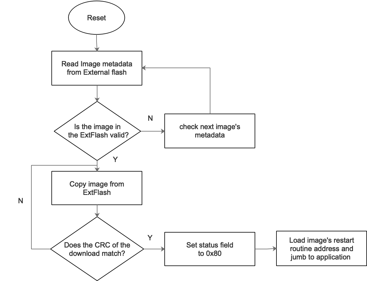
Above shows the high-level functional diagram of offchip BIM. Let’s look under the hood to understand the inner working mechanism of BIM. At BIM startup, it first calls
Bim_checkImages();
Within this function are all the necessary calls made to check whether the OTA image available in the external flash is a valid one or not.
Dissecting the code
/*******************************************************************************
 * @fn     Bim_checkImages
 *
 * @brief  Check for new, valid images in external flash to copy into internal
 *         flash.
 *
 * @param  none
 *
 * @return none
 */
void Bim_checkImages(void)
{
  uint32_t metaDataAddr;

  // Initialize external flash driver.
  if (BLS_init() == -1)
  {
      return;
  }

  for (metaDataAddr = EFL_IMAGE_INFO_ADDR_APP;
       metaDataAddr <= EFL_IMAGE_INFO_ADDR_BLE; metaDataAddr += EFL_PAGE_SIZE)
  {
    // Check for the meta information on the image to see if a download is
    // required.
    Bim_extReadBuf(metaDataAddr, (uint32_t *)&imgInfo, sizeof(ExtImageInfo_t));

    // Check if we have a valid image in external flash.
    if (imgInfo.crc[0] != 0xFFFF && imgInfo.crc[0] != 0x0000 &&
        imgInfo.crc[0] == imgInfo.crc[1] && imgInfo.status == 0xFF)
    {
      while(1)
      {
        uint32_t startAddr;
        uint8_t startPage;

        // Find the image address in external flash.
        if (imgInfo.imgType == EFL_OAD_IMG_TYPE_APP)
        {
          startAddr = EFL_ADDR_IMAGE_APP;
        }
        else if (imgInfo.imgType == EFL_OAD_IMG_TYPE_STACK)
        {
          startAddr = EFL_ADDR_IMAGE_BLE;
        }
        else
        {
          // This is neither Application nor Stack image. Check the next one.
          break;
        }

        // Copy over the image. Note that failure cannot be handled.
        Bim_copyImage(startAddr, (uint32_t)imgInfo.len * EFL_OAD_ADDR_RESOLUTION,
                             (uint32_t)imgInfo.addr * EFL_OAD_ADDR_RESOLUTION);

        startPage = ((uint32_t)imgInfo.addr * EFL_OAD_ADDR_RESOLUTION) /
		            HAL_FLASH_PAGE_SIZE;

        // Check if the CRC of the internal image is valid.
        if (crcCheck(startPage, BIM_IMG_E_OSET, imgInfo.crc))
        {
          // Overwrite the status field of the meta data to reflect the contents of
          // internal flash.
          imgInfo.status = 0x80;

          Bim_extWriteBuf(metaDataAddr, (uint32_t *)&imgInfo,
                          sizeof(ExtImageInfo_t));

          break;
        }
      }
    }
  }

  // Close external flash driver.
  BLS_close();
}
On entry, the BIM reads the 16 byte image metadata from the external flash. The ExtImageInfo_t struct contains all the necessary information including CRC, image version, image length, user-defined image identification, image address, image type, and finally the status field.
BIM first checks if the image on the external flash is valid by checking the CRC and the image info status fields. If valid CRC and CRC shadow fields are found together with the status value as 0xFF, the image is assumed to be valid. After passing the first checkpoint, BIM then checks the image type. Currently, TI’s BIM supports five different types of images:
EFL_OAD_IMG_TYPE_APP                : Application image
EFL_OAD_IMG_TYPE_STACK    		    : stack image
EFL_OAD_IMG_TYPE_NP        		    : network processor image
EFL_OAD_IMG_TYPE_FACTORY		    : factory reset image
EFL_OAD_IMG_TYPE_REMOTE_APP         : remote application image
If a valid image type is found, BIM then copies the image from the respective address on the external flash to the internal. It then computes the CRC of the copied image against the original one from the offchip flash. If the image passed this third checkpoint, it’s now regarded as a valid bootable image, and the status field is set as 0x80 from 0xFF as mentioned above. Overwriting the status field of the metadata to 0x80 reflects that this image has already been copied and prevents the BIM from repeating the above steps for the same image on the next resets.
On the final step, the BIM loads the image’s restart routine address and jumps to the main application. In the current implementation, the application’s start address is 0x1010, aka entry point or interrupt vector.
Important Information: The flash of the device is usually partitioned into different sectors: CCFG, BIM, Application code, Interrupt vector and Image header. This partition is configured in the device load file. For the BIM, the corresponding configuration file is cc13x0_bim_offchip.cmd. The BIM occupies the first page (here as page 0) of the flash starting from address 0x0000 (FLASH_PAGE0_START) to 0x1000 (PAGE_SIZE). This area is simply reserved for the BIM application and its interrupt vectors and no other application should overlap with this.
OK, so let’s get started…
Step 1: Preparing the devices
We will kick-off with TI’s examples to familiarize how the OAD image transfer can be performed between two CC1310 Launchpads. Within this, I will also illustrate how to create an OAD image which will then be sent to the sensor node. The sensor node (or client node) will then receive this updatable image via RF medium, write it to the external flash, and boot the latest application. These steps are necessary to understand how the complete OAD framework works before we can start generating and working with Contiki-NG OTA images. The steps outlined hereafter can also be followed on TI’s resource explorer documentation for OAD server and OAD client.
Creating OAD server image
Import the rfWsnConcentratorOadServer example in CCS from TI_SDK_DIR>/examples/rtos/CC1310_LAUNCHXL/easylink/rfWsnConcentratorOadServer. Then compile the application in CCS by going to Projects -> Build project. After the project has been built successfully, load the firmware into the OAD_server launchpad.
The OAD_server will display the following on the UART terminal.
Creating the BIM image
Next, import the boot image manager application example from TI_SDK_DIR>/examples/rtos/CC1310_LAUNCHXL/easylink/bim_offchip. Then compile the application in CCS. After the project has been built successfully, it will generate bim_extflash_cc13x0lp.hex located in the directory workspace_v10/bim_extflash_cc13x0lp/FlashOnly/bim_extflash_cc13x0lp.hex. For now just copy bim_extflash_cc13x0lp.hex to a separate folder and we will use it in the later steps.
Creating OAD client image
Now import the rfWsnNodeExtFlashOadClient example in CCs from TI_SDK_DIR>/examples/rtos/CC1310_LAUNCHXL/easylink/rfWsnNodeExtFlashOadClient. Note, the project name should be rfWsnNodeExtFlashOadClient. Compile the application and copy the rfWsnNodeExtFlashOadClient_CC1310_LAUNCHXL_tirtos_ccs.hex.
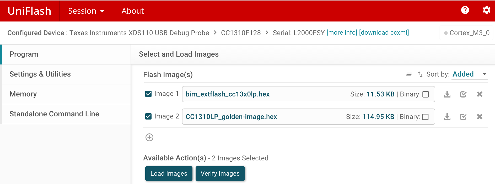
Connect the OAD_client launchpad and start the UniFlash application. Choose the correct launchpad device and click start. Then go to the Settings & Utilities panel on the left hand side, navigate to the manual erase option.
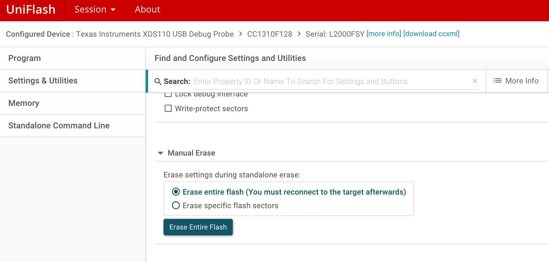
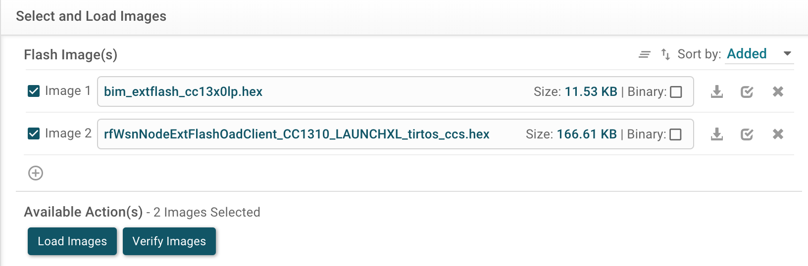
Erase Entire Flash of the OAD_client. After erase, go to Program menu, and select the two images in the UniFlash that we generated above in CCS,mainly: The bootloader image Bim_extflash_cc13x0lp.hex and the application image rfWsnNodeExtFlashOadClient_CC1310_LAUNCHXL_tirtos_ccs.hex. Both the images can be added to UniFlash by clicking the + button.
Flash the images into the OAD_client launchpad. After reset, OAD_client should display the following on the terminal.
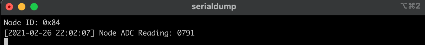
As explained earlier, let’s inspect the flash sector configuration of the application app for rfWsnNodeExtFlashOadClient defined in CC1310_LAUNCHXL_TIRTOS_OAD.cmd. You will notice that for offchip mode, the application starts from address 0x1010 (FLASH_BASE) while its 16 bytes metadata or header starts from page 1 address 0x1000 (0x1010 - 0x1000 = 16 bytes). In the next steps, we will see how this information adds up when creating the OAD image.
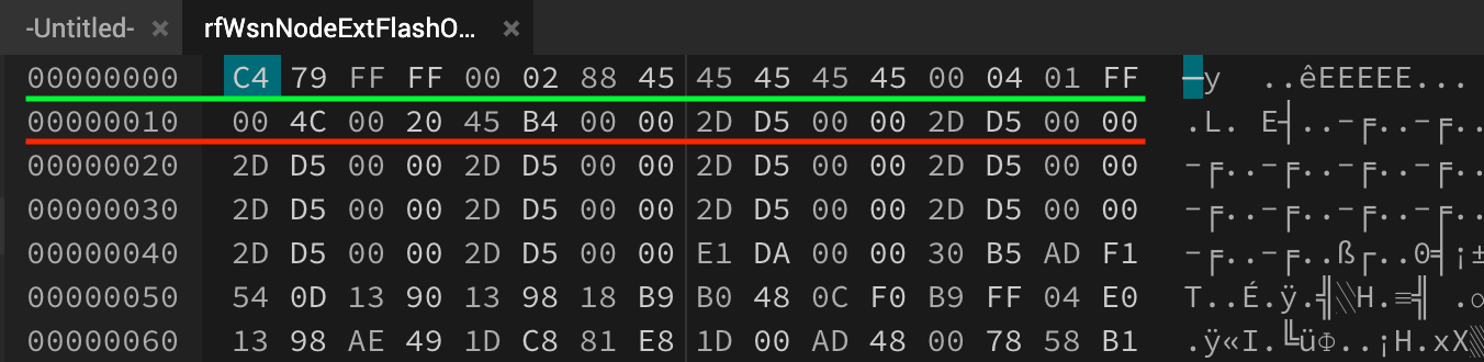
Let’s inspect the raw .hex file of the OadClient to see what all this means. Here you will notice that the application information starts from address 0x1010 and onwards. Since this is not an OTA image, there is no metadata/ header information which will be located at address 0x1000. That’s it.
Step 2: Performing an OAD Image transfer
Generating OAD images
For generating the OTA downloadable images we will use the tools provided by the TI in the Simplelink SDK. The OAD binary can be created from the application .hex using the OAD image tool found in the following location: TI_SDK_DIR>/tools/common/oad/oad_image_tool.py. The python scripts used in this tutorial are also available in the git repo of this tutorial under oad-tools.
Generate the application .hex file from the project rfWsnNodeExtFlashOadClient. To keep track of client node firmware, let’s first change the FW version string in oad/native_oad/oad_client.c
#define FW_VERSION "v1.0" to #define FW_VERSION "v2.0"
and then compile the project.
Copy the generated rfWsnNodeExtFlashOadClient_CC1310_LAUNCHXL_tirtos_ccs.hex and rename it to rfWsnNodeExtFlashOadClient_CC1310_LAUNCHXL_app_v2.hex. Place the .hex and oad_image_tool.py script in the same directory.
To create the OAD image using the image creation tool, execute the following command:
python oad_image_tool.py -t offchip -i app -v 0x0200 -m 0x1000 -ob rfWsnNodeExtFlashOadClient_CC1310_LAUNCHXL_app_v2.bin rfWsnNodeExtFlashOadClient_CC1310_LAUNCHXL_app_v2.hex
The following command-line arguments are used to build the image:
- -t offchip selects the type of OAD image to be offchip
- -i app is used to indicate the BIM is not included and contains only the application image (EFL_OAD_IMG_TYPE_APP)
- -m 0x1000 indicates the start of the image (including the header)
- -v 0x0200 refers to the FW version with the format 0xXXYY where XX is the major version and YY the minor version (for example 3.0 would be 0x0300).
After successful creation of the OAD binary (xx.app_v2.bin), the following will be displayed on the terminal showing the metadata / image header information embedded into the application image binary.
Writing to:
rfWsnNodeExtFlashOadClient_CC1310_LAUNCHXL_app_v2.bin
***********************************************************************************
Success
***********************************************************************************
The script has calculated the 16 Byte OAD Metadata vector below

Bytes: | 0 - 2  |  2 - 4   | 4 - 6  | 6 - 8  |  8-12    | 12 - 14 |   15    |  16  |
Desc : |  CRC   | CRC-SHDW | imgVer | imgLen |  usrId   | imgAddr | imgType | stat |
------------------------------------------------------------------------------------
Data : | 0x79C4 |  0xFFFF  | 0x0200 | 0x4588 |  EEEE    | 0x0400  |  0x01   | 0xFF |
***********************************************************************************
One would notice that this is all the information that is required by the BIM for evaluating an OTA image before booting-in (refer to section: Boot Image Manager (BIM) for offchip OAD).
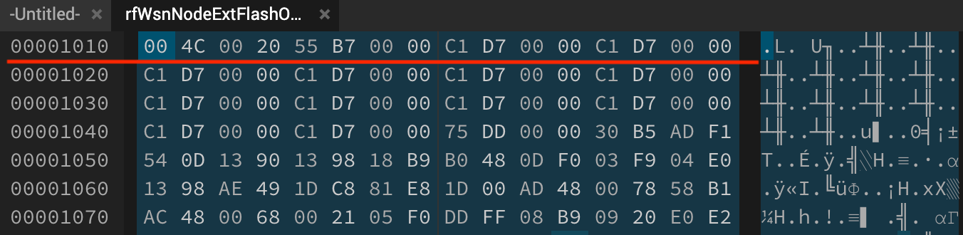
Let’s inspect the raw OAD binary (rfWsnNodeExtFlashOadClient_CC1310_LAUNCHXL_app_v2.bin) that has been created by the python oad_image_tool to see what all this means. Here you will notice that the first row (indicated by the green line) or the starting addresses contain the 16 bytes metadata followed by the application data in the second row (red line). Note: the metadata is written in little endian format, for instance: 2 byte CRC = 0x79C4 is embedded as C4 79 and likewise.
This is the OAD image that we will send over the server to the client for updating the device firmware.
Loading the OAD image to the server launchpad
First, the node OAD image (rfWsnNodeExtFlashOadClient_CC1310_LAUNCHXL_app_v2.bin) needs to be uploaded into the external flash of the OAD server which will be sent to the client. This can be achieved by writing the image via the UART of the OAD server using the oad_write_bin.py script.
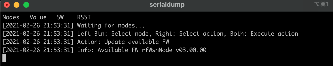
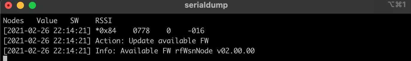
This action must first be selected using BTN-2. Press BTN-2 until the Action is set to Update available FW, then press BTN-1 and BTN-2 simultaneously on the CC1310 launchpad to execute the action. When “Available FW” is selected the terminal will display:

Close the UART terminal to free the COM port before executing the python script (make sure to choose the correct Launchpad COM port).
python oad_write_bin.py /dev/tty.usbmodemL2000FSY1 rfWsnNodeExtFlashOadClient_CC1310_LAUNCHXL_app_v2.bin
Once the writing process starts, terminal will display:
After the download is complete, the UART terminal can be reopened and the “Info” menu line will be updated to reflect the new FW available for OAD to a client node. Since we build the image with argument -v 0x0200, it will display the available firmware as version 2 (v02.00.00)
Transferring the OAD image to the client node
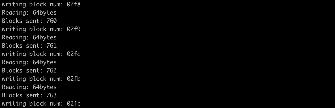
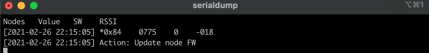
The client node FW can now be updated to the image stored on the external flash of the server. Press BTN-1 on the server launchpad until the desired node is selected, then press BTN-2 until the Action is set to Update node FW. To execute the action, press BTN-1 and BTN-2 simultaneously. The next time the node sends data, the OAD sequence will begin. As the node requests each image block from the server the OAD server display is updated to show the progress of the image transfer.
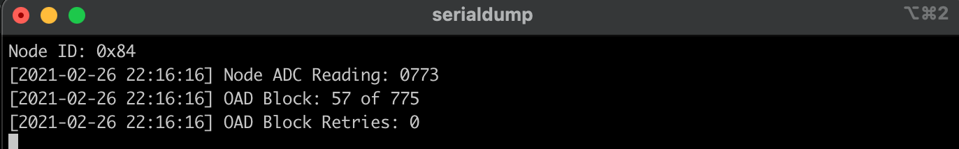
The client node display will also update to show the status of the image transfer.
Once the OAD has completed successfully, the server will indicate that the transfer has finished with an OAD Complete status. The client node will then reset itself with a new node ID. If the device does not reset itself a manual reset may be necessary.
The next time the client node sends data to the concentrator, the FW version of the selected node will appear in the Info section as v2.0 confirming that the OAD was successful and that the new image has been accepted by the BIM and booted into by the device.
Congratulations! you have completed your first over-the-air firmware update. Next, we will start implementing the OAD for Contiki-NG OS.
Implementing offchip over-the-air download for Contiki-NG
It is assumed that the user has already installed the latest version of Contiki-NG and set up the environment for compiling the firmware. If not, please refer to the ContikiNG wiki page to complete the setup procedure.
Step 1: ContikiNG application source
Let’s get started with the ContikiNG application so that we can build a golden image that can be flash together with the bootloader. This is required to see if all the settings in terms of the flash sector, image starting address, and interrupt vector configurations are correct and can be booted by the BIM.
Copy the application firmware source folder simplelink-cc1310-oad from git repo and place it in the contiki-ng/examples directory. The source file has been designed to contain all the necessary configurations required for OAD application development without changing any inner Contiki-NG source files keeping the OS intact and standardized.
Let’s delve into the golden-image source directory which contains six different files.
- golden-image.c is the main application source file which will just print hello world every 5 seconds.
- Makefile is used by Contiki-NG to compile the main application.
- Makefile.common is a custom file configuration that copies and renames the .hex once the compilation is complete.
- Makefile.target specifies the target platform in ContikiNG. This tutorial currently only supports target as simplelink and board launchpad/cc1310.
- project-conf.h contains the configurations related to the target platform.
- oad.lds is a custom load script that configures the flash area for BIM and OAD images. This is the key file for configuring the application start address, length, and the reset vector used by the BIM to start the main application.
Within the oad.lds, the main configuration parameters are:
FLASH_BASE = 0x1010;
FLASH_SIZE = 0x1EFF0;
_resetVecs_base_addr;
FLASH_BASE defines the starting address of the application in flash which is from address 0x1010 and can occupy a maximum length of 0x1EFF0 (FLASH_SIZE).
_resetVecs_base_addr which is defined to be the same as FLASH_BASE is used by the bootloader as an application image’s entry point, here as 0x1010. These configuration parameters have been kept the same as found in rfWsnNodeExtFlashOadClient’s .cmd. In addition, this allows one to use the TI’s BIM example without any changes or develop their own bootloader for ContikiNG.
Step 2: Generating the golden image in Contiki-NG
At this point, we are all set to start generating the BIM compatible application image in ContikiNG. To compile the golden-image, open the terminal in the example/simplelink-cc1310-oad/golden-image directory and execute the following:
make clean && make DESCR=golden-image golden-image.rename
This will compile and create CC1310LP_golden-image.hex. Great start. Next, connect one of the launchpads, start UniFlash and Erase Entire Flash of the connected device. After erasure, go to Program menu, and select these two images in the UniFlash mainly:
The bootloader image Bim_extflash_cc13x0lp.hex and the application image CC1310LP_golden-image.hex that we just generated above in ContikiNG. All the images are also provided in the git repo of this tutorial.
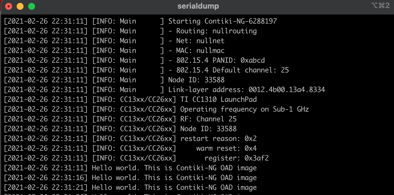
Load images to the launchpad and start a terminal program. After hitting reset, the following will be displayed on the terminal. This indicates that the TI’s bootloader and the Contiki golden image are running in harmony and all the required configurations are correct.
Step 3: Generating Contiki OAD image
One of the advantages of keeping the configurations similar to that required by the TI’s bootloader is that now using the same toolchains as above we can create an OAD compatible image in ContikiNG.
Lets compile the same golden-image and this time we will rename the output .hex to be CC1310LP_oad-v2.hex. Place the CC1310LP_oad-v2.hex and oad_image_tool.py script in the same directory.
To create the OAD binary image from .hex using the image creation tool, execute the following command:
python oad_image_tool.py -t offchip -i app -v 0x0200 -m 0x1000 -ob CC1310LP_oad-v2.bin CC1310LP_oad-v2.hex
After successful creation of the OAD binary (CC1310LP_oad-v2.bin), the following will be displayed on the terminal showing the metadata / image header information embedded into the application binary.
Writing to:
CC1310LP_oad-v2.bin
******************************************************************************************
Success
******************************************************************************************

The script has calculated the 16 Byte OAD Metadata vector below

Bytes: | 0 - 2  |  2 - 4   | 4 - 6  | 6 - 8  |  8-12    | 12 - 14 |   15    |  16  |
Desc : |  CRC   | CRC-SHDW | imgVer | imgLen |  usrId   | imgAddr | imgType | stat |
------------------------------------------------------------------------------------
Data : | 0xB2A3 |  0xFFFF  | 0x0200 | 0x3068 |  EEEE    | 0x0400  |  0x01   | 0xFF |
******************************************************************************************
Step 4: Transferring the OAD image to the node for testing and verification
Here, we are going to use the same OAD server as a medium to transfer and write the image to the node’s external flash which is to be expected, for instance, this can be the sensor device running Contiki application. The OAD client will act as a receiver that will receive the OTA firmware over the RF channel sent by the server and then write this image to its external flash of the CC1310 Launchpad.
Load the CC1310LP_oad-v2.bin to the OAD server by pressing BTN-2 until the Action is set to Update available FW, then press BTN-1 and BTN-2 simultaneously on the CC1310 launchpad to execute the action.
Execute the following command to load the image making sure to choose the correct COM port:
python oad_write_bin.py /dev/tty.usbmodemL2000FSY1 CC1310LP_oad-v2.bin
To initiate image transfer to the client node, press BTN-1 on the server launchpad until the desired node is selected, then press BTN-2 until the Action is set to Update node FW. To execute the action, press BTN-1 and BTN-2 simultaneously.
Once the OAD has completed successfully, the server will indicate that the transfer has finished with an OAD Complete status. The client node will then reset itself. If the device does not reset itself a manual reset may be necessary. After the reset, you will see the device bootup the new contiki image.
Congratulations! you have completed your over-the-air firmware update of the ContikiNG image.